ALLPCB


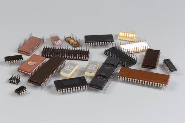
Early MCUs had limited on-chip peripherals such as UART, I2C, and SPI, which necessitated the use of software-based simulation, often called bit-banging. This article explores several methods for simulating a serial port using general-purpose IO (GPIO) pins, offering a deeper understanding of level-based communication protocols.
The Need for GPIO Serial Port Simulation
Many modern high-performance MCUs offer numerous serial peripherals. The STM32F103 series, for example, provides up to five USARTs. However, typical projects may only use a few of these. The ability to remap peripheral pins also provides some flexibility for projects with a high demand for serial ports.
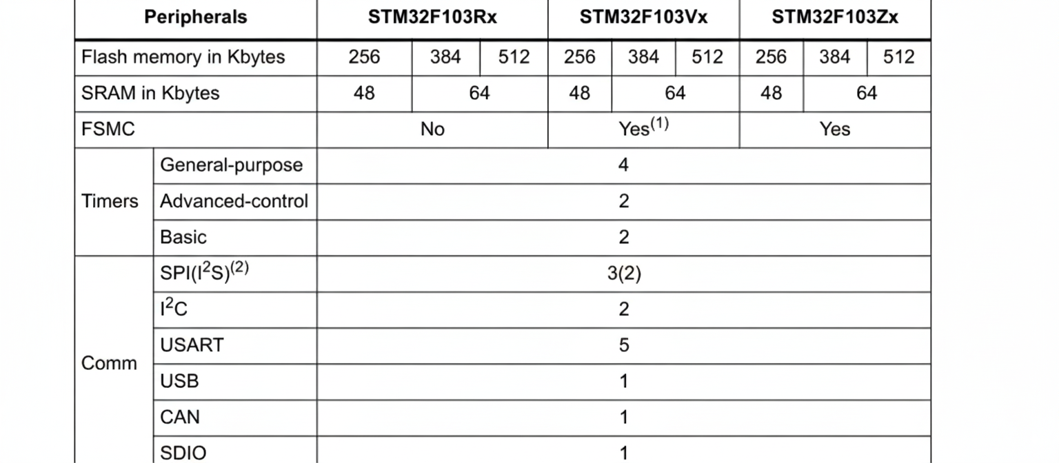
Source: STMicroelectronics Datasheet
In system integration projects, serial communication is a common interface. However, different devices may use proprietary protocols or varying serial port configurations (baud rate, data format, etc.). This high demand for serial ports often becomes a key factor in MCU selection.
The software for these systems is often straightforward, focusing on tasks like data transmission, reception, and forwarding. This means a high-performance controller is not always necessary, making a software-based serial port implementation a practical and cost-effective solution.
Principle of GPIO Serial Port Simulation
Most communication protocols transmit signals using voltage levels, where a high level represents a '1' and a low level represents a '0'. By establishing rules for the timing of these levels, devices can parse the data and exchange information. To understand how to simulate a serial port, let's first review its physical communication format.
Physical Communication Format
The following example uses a common format: 8 data bits, 1 stop bit, and no parity.