ALLPCB


Powering IEPE Sensors
Figure 1 shows a basic schematic of a power unit used with IEPE sensors.
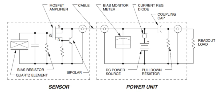
First, a well-regulated DC supply and a constant-current element are required to power the sensor. The DC supply typically provides 18 to 30 V. Current regulation can be implemented with a current-regulating diode (CRD). A CRD supplies a near-constant current regardless of voltage fluctuations and load resistance changes, and can maintain a constant current over a wide voltage range from less than 1 V up to about 100 V. The schematic symbol for a CRD is shown below.
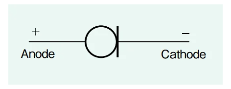
Although most IEPE sensors are powered by a 2 to 4 mA current source, some applications require up to 20 mA. CRDs are commonly rated at 4 mA. For higher currents, multiple CRDs can be paralleled or a higher-capacity constant-current circuit can be used.
Note that supplies without current limiting must not be used to power IEPE sensors, as the sensor can be damaged immediately.
IEPE power units often include a voltmeter to monitor the sensor bias voltage and indicate system status (short, open, or normal). For IEPE sensors, the output signal and supply bias are both carried on the same two-wire connection.
As shown in Figure 1, many IEPE power units use a coupling capacitor to separate the AC signal from the DC bias. Some units use DC coupling to avoid reducing the discharge time constant of the system.
Typical IEPE System Options
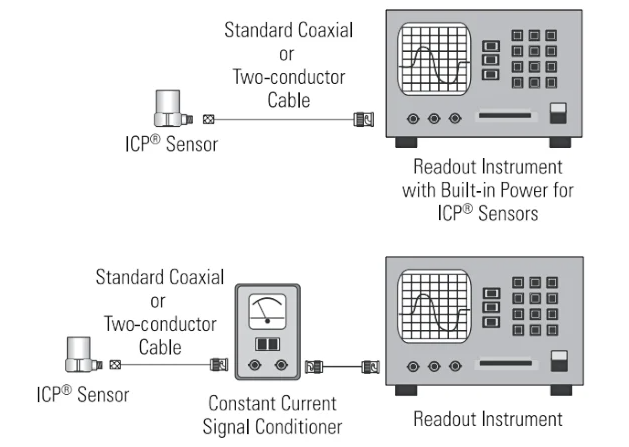
There are two options to power IEPE sensors. Some readout instruments include a built-in constant-current source specifically for IEPE sensors. If the readout device lacks an IEPE supply, an external power unit should be used.
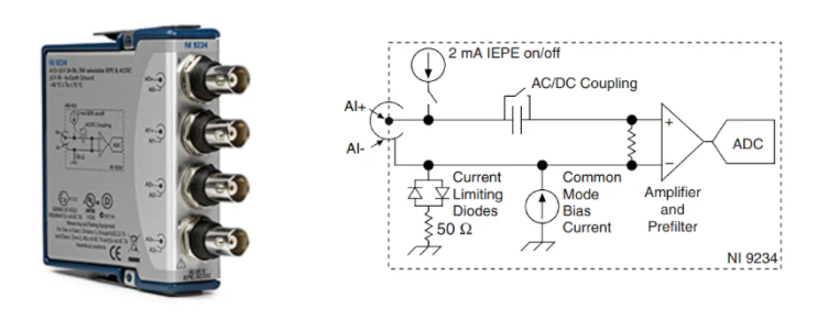
Example IEPE Readout Device
Figure 4 shows an example readout module that supports IEPE sensors. The module depicted includes a 2 mA constant-current source and AC coupling option as indicated by its input circuit.
Typical Charge-Output (Non-IEPE) System
Figure 5 shows a typical measurement system based on a charge-output piezoelectric sensor, i.e., a sensor without an integrated preamplifier.
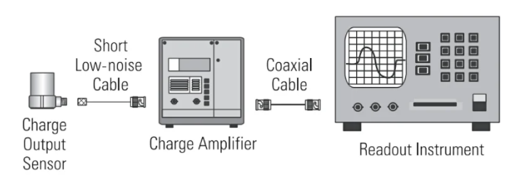
In this case an external charge amplifier is required to convert the sensor's charge output into a voltage. A shielded, low-noise coaxial cable must be used to connect the sensor to the charge amplifier to minimize triboelectric noise. Between the charge amplifier and the readout instrument, standard coaxial cable may be used.
IEPE Sensors vs Charge-Output Sensors
Most current applications use IEPE sensors, but charge-output sensors have distinct advantages in some situations. The following sections compare the main trade-offs.
Operating Temperature Range
The built-in electronics of an IEPE sensor set an upper limit on the operating temperature. For standard electronic components the limit is typically around 125°C; using specialized components can raise this limit to around 165°C.
By contrast, charge-output sensors contain no internal electronics, so their high-temperature limit is set by the Curie temperature of the piezoelectric material. The Curie temperature is the point at which the material loses its piezoelectric properties. Charge-output sensors can operate at temperatures up to about 700°C.
Besides the Curie temperature, the insulation resistance of materials used in charge-output sensors also constrains the operating temperature. Insulation resistance can drop significantly at elevated temperatures, which may cause charge amplifier drift. Connecting a general-purpose charge amplifier to a sensor with very low insulation resistance can produce drift and other unexpected frequency-response characteristics. Figure 6 shows the frequency response of a charge amplifier connected to a low-resistance sensor.
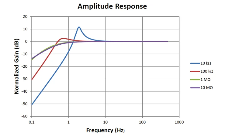
When insulation resistance is very low, the system amplitude response can show peaks exceeding 10 dB at the low end of the required frequency range. For high-temperature applications, choose a charge amplifier designed to handle very low insulation resistance while maintaining a flat frequency response.
Cable Requirements
Charge-output sensors require specially treated cable to minimize triboelectric noise, which is unwanted charge generated when two different materials rub together. Cable bending or vibration can induce this noise. The high-impedance output of a non-IEPE sensor is susceptible to such noise, so low-noise special-purpose cable is needed between the sensor and the charge amplifier. These cables are typically more expensive and increase system cost.
Also, the high-impedance output of a charge sensor limits line-driving capability, generally restricting cable length between sensor and charge amplifier to about 10 meters. By comparison, IEPE sensors provide a low-impedance output that can be transmitted over standard coaxial cable for relatively long distances without significant noise increase.
Flexibility in Adjusting Sensor Parameters
For IEPE sensors, parameters such as sensitivity and time constant are fixed at manufacture. External electronics can amplify or attenuate the sensor output, but cannot change the sensor's intrinsic sensitivity or time constant. Charge-output sensors produce a raw charge signal that is processed by an external charge amplifier, offering greater flexibility to adjust system parameters such as the time constant. Specialized charge amplifiers can provide very long time constants, extending the system's low-frequency response.