ALLPCB


Definition
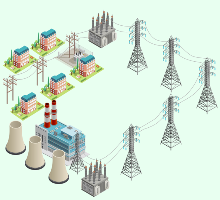
High-voltage switchgear refers to electrical apparatus used in power generation, transmission, distribution, energy conversion, and consumption for making, breaking, controlling, or protecting circuits at voltage levels from 3.6 kV to 550 kV. It mainly includes high-voltage circuit breakers, high-voltage isolating and earthing switches, high-voltage load switches, automatic reclosing devices and sectionalizers, operating mechanisms, explosion-proof distribution devices, and switchgear assemblies. High-voltage switchgear manufacturing is an important part of transmission and transformation equipment manufacturing and plays a key role in the power industry. Some refer to high-voltage switchgear as high-voltage distribution cabinets; they are essentially the same equipment.
Function
High-voltage switchgear supports overhead and cable line entry, bus coupling, and related functions.
Application
Suitable for power plants, substations, power system switching stations, petrochemical plants, steel rolling mills, light industry and textile plants, industrial sites, residential complexes, and high-rise buildings.
Composition
The switchgear shall meet the requirements of AC metal-enclosed switchgear standards and is mainly composed of the enclosure and the circuit breaker. The enclosure contains the shell, electrical components (including insulating parts), various mechanisms, secondary terminals and wiring, and related compartments.
Five Safety Interlocks
- Prevention of closing under load: When the withdrawable vacuum circuit breaker is in the test position, the truck cannot be moved into the service position for closing.
- Prevention of closing with the earthing switch closed: When the earthing switch is closed, the circuit breaker truck cannot be closed.
- Prevention of access to live compartments: When the vacuum circuit breaker is closed and in service, the rear door is mechanically interlocked with the earthing switch so the door cannot be opened.
- Prevention of earthing switch closing while energized: When the vacuum circuit breaker is in service and closed, the earthing switch cannot be closed.
- Prevention of withdrawing the truck under load: When the vacuum circuit breaker is in service and closed under load, the truck cannot be withdrawn from the service position.
Structural Components
The main components include the enclosure, high-voltage vacuum circuit breaker, energy storage mechanism, withdrawable truck, earthing switch, and integrated protection relay.
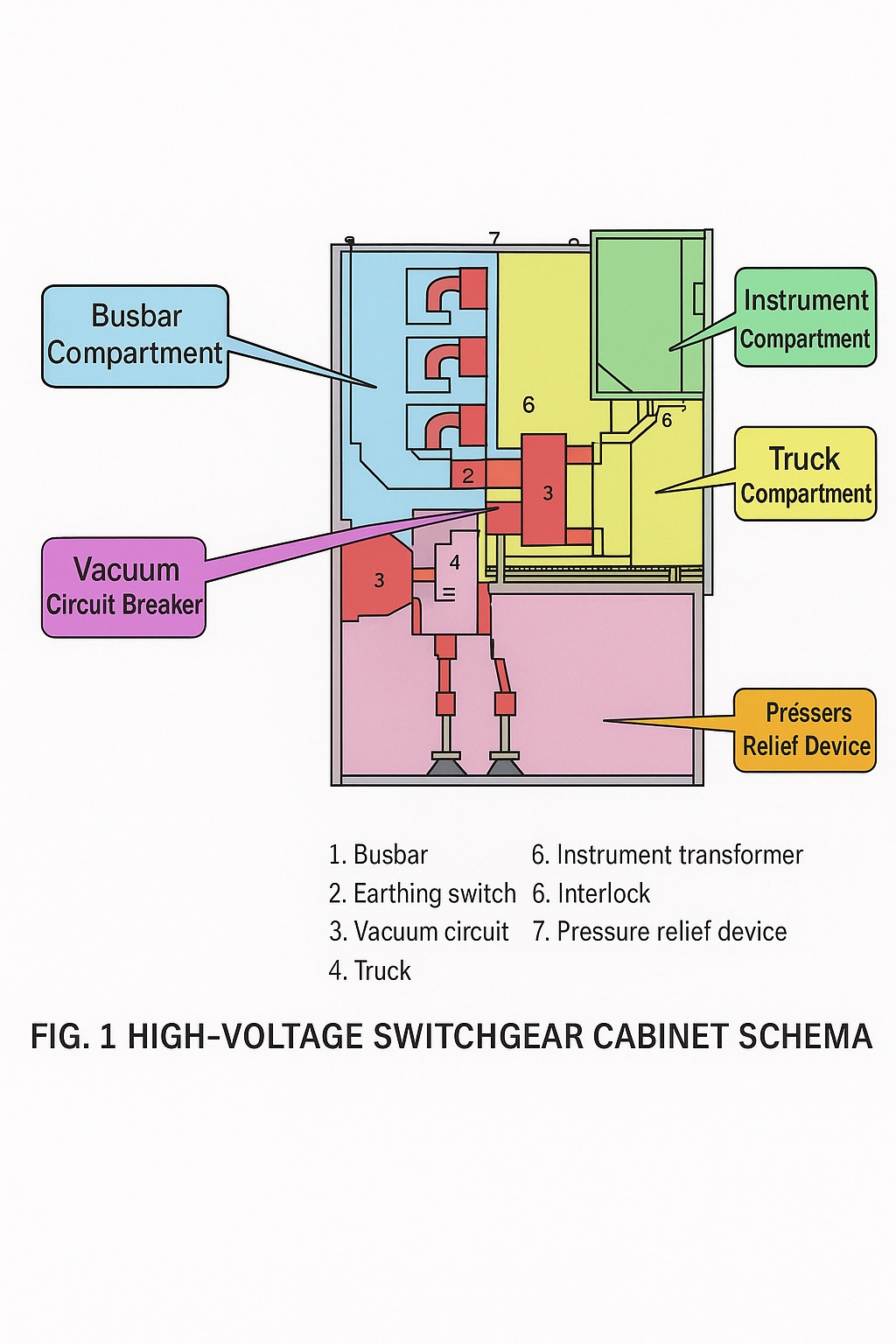
Enclosure
The enclosure is formed from pressed steel plates and is a metal-enclosed structure with separate compartments such as instrument compartment, truck compartment, cable compartment, and busbar compartment. Compartments are separated by metal partitions. The instrument compartment houses the integrated protection relay, ammeter, voltmeter, and related devices; the truck compartment houses the withdrawable truck and high-voltage vacuum circuit breaker; the busbar compartment contains the three-phase busbars; the cable compartment provides external connections for power cables.
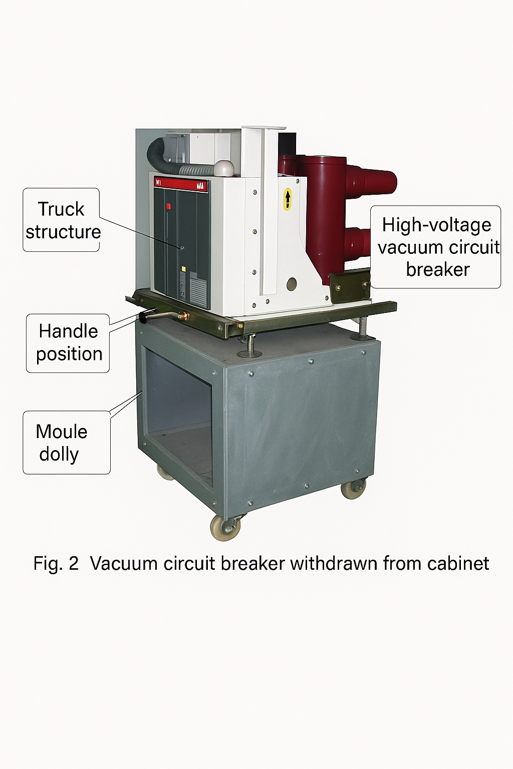
High-Voltage Vacuum Circuit Breaker
The high-voltage vacuum circuit breaker locates its main contacts within a sealed vacuum chamber. When contacts make or break, the arc has no gaseous support and is extinguished without burning, giving long service life. The breaker is mounted on an insulating base to improve the insulating performance, hence the name vacuum circuit breaker.
Withdrawable Truck Mechanism
The vacuum circuit breaker is mounted on a withdrawable truck. By operating the truck handle, the truck moves in and out of the enclosure. Turning the handle clockwise inserts the breaker into the high-voltage circuit; turning it counterclockwise withdraws the breaker from the circuit.
Energy Storage Mechanism
An electric motor drives a spring-based energy storage mechanism. The stored spring energy is released to close the vacuum circuit breaker.
Earthing Switch
The earthing switch is an interlock device. The enclosure doors can only be opened when the earthing switch is closed; if the earthing switch is open, the doors remain locked, providing safety interlock protection.
Integrated Protection Relay
The integrated protection relay is a microprocessor-based protection device consisting of a microcontroller, display, keys, and peripheral circuits. It replaces traditional overcurrent, overvoltage, and timing relays. Input signals include current transformers, voltage transformers, residual current transformers, and digital inputs. Settings such as current, voltage, instantaneous trip time, and start time are configurable via the keypad. The display shows real-time data and participates in control and protection actions.
Types and Configurations
- By main circuit wiring: bridge connection, single bus, double bus, single bus sectionalized, double bus with bypass bus, and single bus sectionalized with bypass bus.
- By breaker installation: fixed switchgear and withdrawable (truck-type) switchgear.
- By enclosure structure: metal-enclosed compartmentalized, metal-enclosed armored, and metal-enclosed fixed box-type switchgear.
- By truck installation position: floor-mounted and center-mounted switchgear.
- By internal insulation medium: air-insulated switchgear and SF6 gas-insulated switchgear.
Main Technical Parameters
- Rated voltage, rated current, rated frequency, rated power-frequency withstand voltage, and rated lightning impulse withstand voltage.
- Circuit breaker rated short-time breaking current, rated closing peak current, rated short-time withstand current, and rated peak withstand current.
- Earthing switch rated closing peak current, rated short-time withstand current, and rated peak withstand current.
- Operating mechanism closing and opening coil rated voltage, DC resistance, and power; energy storage motor rated voltage and power.
- Enclosure protection level and applicable standard numbers.
Power-On Procedure
- Close and lock all rear doors and rear cover plates. The rear door can only be closed when the earthing switch is open.
- Insert the earthing switch operation handle into the hexagonal hole at the lower right of the middle door and rotate it counterclockwise to place the earthing switch in the open position. The interlock plate will automatically cover the operation hole and lock the lower door.
- Raise the service trolley to its parked position, push the withdrawable truck into the enclosure to the interlock position, manually engage the secondary connector, and close the truck compartment door.
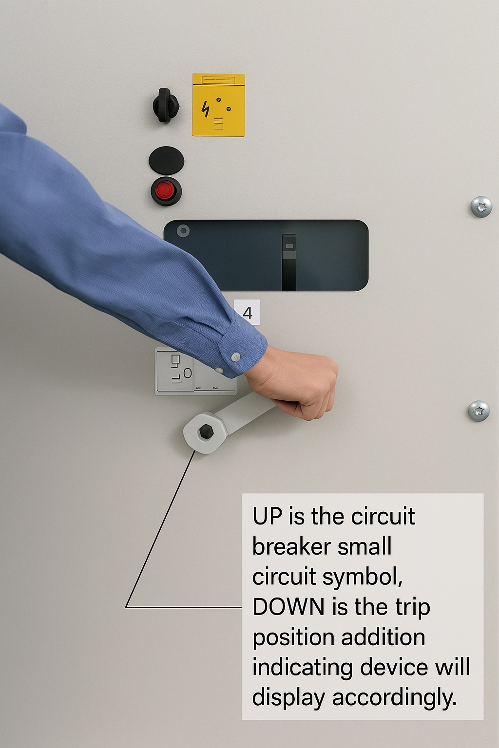
- Insert the truck crank into the crank socket and rotate clockwise about 20 turns. When the crank feels noticeably resisted and a clicking sound is heard, remove the crank. The truck is now in the service position, the secondary connector is locked, and the main circuit of the breaker is connected. Verify related signals.
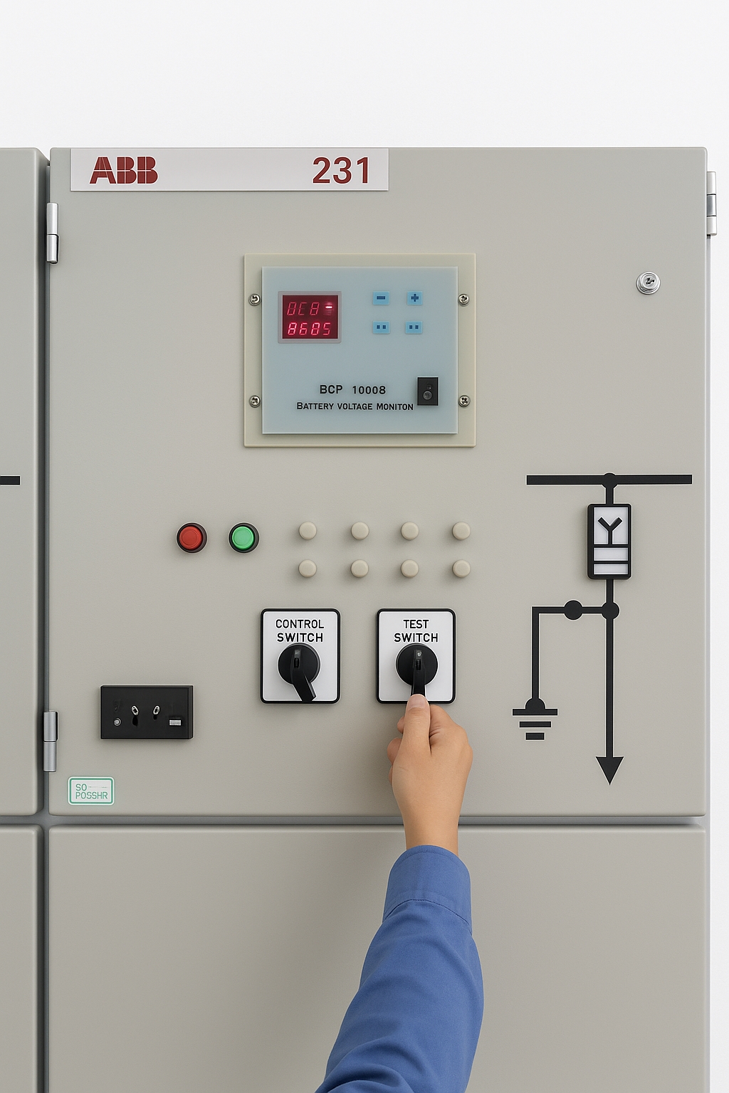
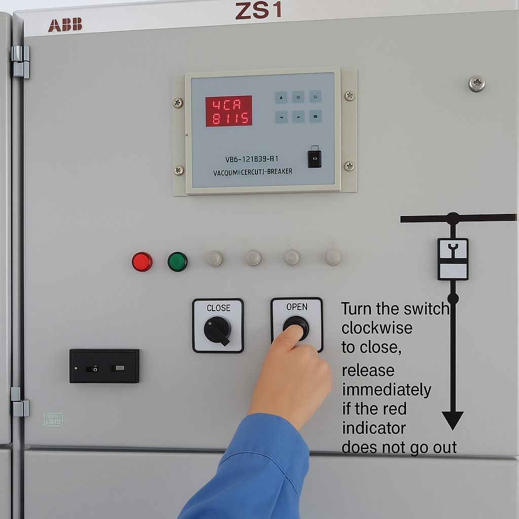
- Operate the close/open selector on the instrument panel to close the breaker and energize the circuit. The green indicator on the panel will go off and the red indicator will light, indicating successful closing.
Power-Off Procedure
- Set the close/open selector on the instrument panel to the open position so the breaker opens and is placed in the test position. The red indicator will go off and the green indicator will light, indicating successful opening.
- Insert the truck crank into the crank socket and rotate clockwise about 20 turns. When the crank is noticeably resisted and a clicking sound is heard, remove the crank. The truck is now in the test position, the secondary connector lock is released. Open the truck compartment door, manually disengage the secondary connector, and verify the main circuit is disconnected.
- Raise and lock the service trolley, withdraw the truck onto the service trolley, and open the service trolley.
- Check a voltmeter or use a voltage detector to confirm the circuit is de-energized before proceeding.
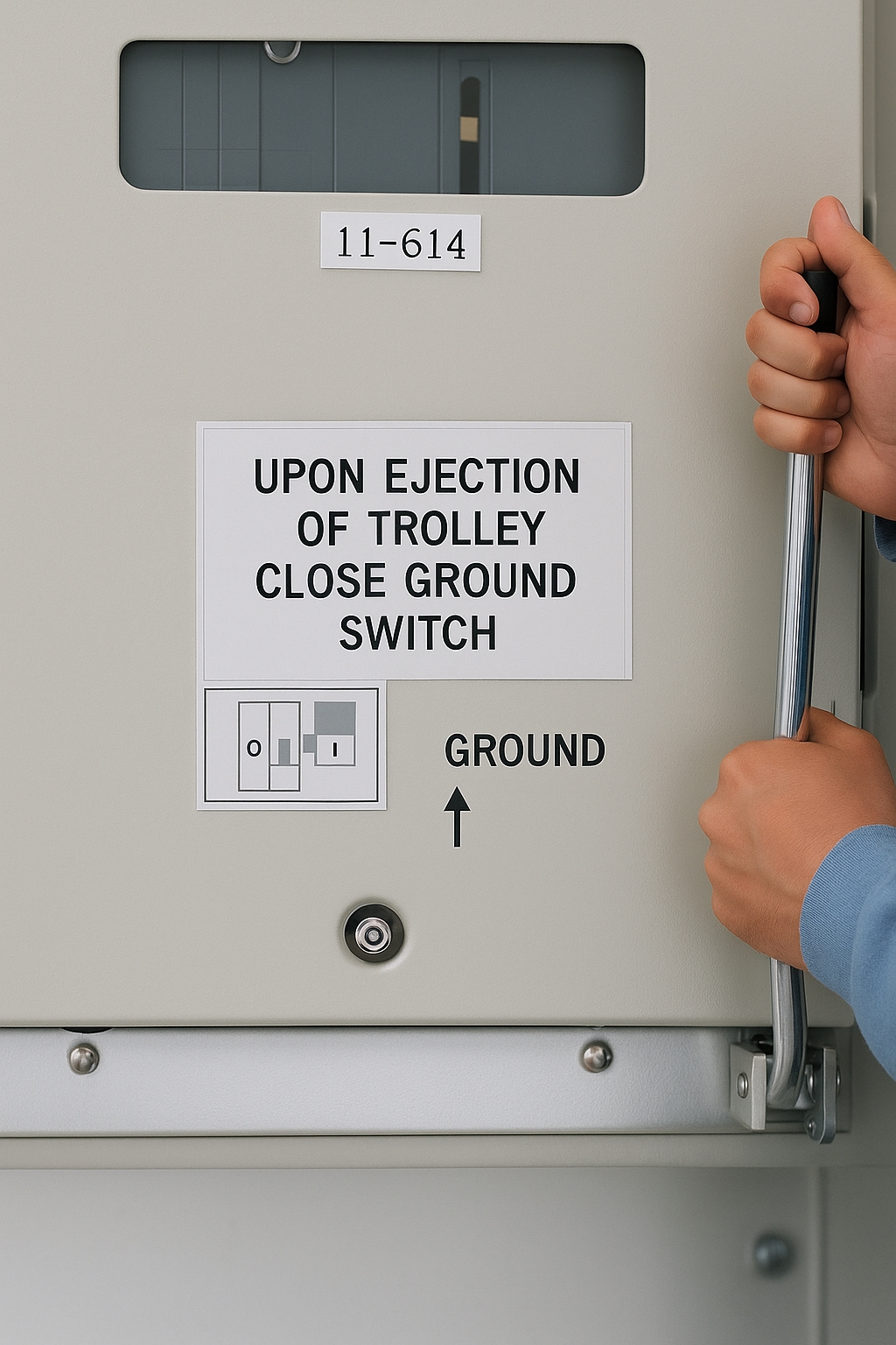
- Insert the earthing switch operation handle into the hexagonal hole at the lower right of the middle door and rotate clockwise to close the earthing switch. After confirming the earthing switch is closed, open the lower door and maintenance personnel may enter for inspection or repairs.
Closing Fault Diagnosis and Handling
Closing failures can be categorized as electrical faults or mechanical faults. Closing can be performed manually or electrically. If manual closing is not possible, the issue is usually mechanical. If manual closing is possible but electrical closing is not, the issue is electrical.
1. Protection Operation
If a line fault exists before energizing, protection circuits will operate and prevent closing via the anti-pumping relay. After closing, the breaker will trip immediately. Even if the selector remains in the close position, the breaker will not reclose repeatedly.
2. Interlock Protection Faults
Modern switchgear includes the five safety interlocks, which require the breaker not be in service or test position to allow closing. In practice this occurs when a position switch is not closed, preventing electric closing. In such cases, the service or test position indicator will not light. Slightly move the truck until the limit switch closes, then closing is permitted. If the limit switch is grossly misaligned, adjust it. In JYN-type switchgear, if the position switch cannot move outward, a V-shaped shim can be added to ensure reliable limit switch closure.
3. Electrical Interlock Faults
Electrical interlocks are used to ensure reliable system operation. For example, in a single-bus sectionalized system with two incoming feeds, the two incoming feeders and the tie bay are interlocked so only two of the three breakers can be closed simultaneously to avoid backfeeding and increased parallel short-circuit currents. The interlock circuit is implemented by series and parallel arrangements of normally open and normally closed contacts. When electric closing is not possible, first check for electrical interlocks; do not attempt blind manual closing. Electrical interlock faults are often due to improper operation, such as a withdrawn truck inside a feeder cabinet whose plug is not engaged. If the interlock circuit is suspected faulty, use a multimeter to locate the fault.
Using the red and green indicator lights to judge auxiliary switch faults is simple but not always reliable. A multimeter can be used to confirm the fault. Auxiliary switch repair methods include adjusting the flange angle or changing the length of the auxiliary switch linkage.
4. Control Circuit Open-Circuit Faults
Damage to control switches or broken wires in the control circuit can prevent the closing coil from receiving power. In this case the closing coil will not operate and there is no audible action. Measure the voltage across the coil terminals; no voltage indicates an open circuit. Use a multimeter to locate the open point.
5. Closing Coil Faults
A burned closing coil indicates a short circuit fault and may produce odor, smoke, or blown fuses. Closing coils are designed for short-time operation and must not be energized for prolonged periods. After a failed closing attempt, determine the cause rather than repeatedly attempting to close. CD-type electromagnetic operating mechanisms, which carry higher currents, are particularly susceptible to coil damage if repeatedly operated.
When troubleshooting a switchgear that will not close, a trial energization method is often used. This helps rule out line faults (except transformer temperature or gas protection faults), electrical interlock faults, and limit switch faults. If the fault appears inside the truck, temporary use of the test position for trial energizing or replacing the truck with a spare one can restore power quickly and reduce outage time.