ALLPCB


Overview
The overall approach for implementing a power distribution system: design the distribution system based on screen power consumption, on-site construction requirements, and the loads carried by each distribution cabinet.
Implementation Steps
- Calculate the maximum power of the full screen.
- Select a distribution cabinet sized for the maximum screen load.
- Choose bus conductors and a bus routing plan based on the cabinet load.
- Allocate distribution according to the screen layout and each cabinet's maximum power, and select appropriate conductors.
- Perform site wiring integrating the bus, distribution cabinets, and the display panels.
Case Study
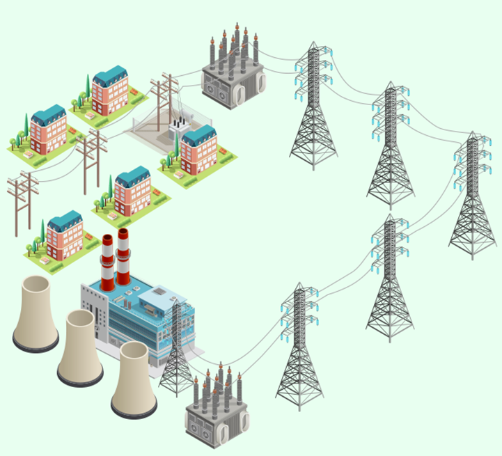
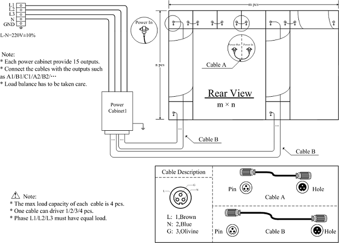
The following analysis is based on a generic power distribution connection diagram:
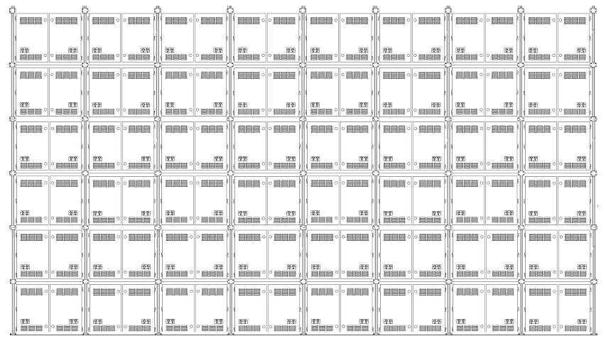
Example: P8 full-color, layout 8 wide x 6 high.
- Calculate maximum power. Single cabinet maximum power: 1000 W. Full screen total: 48 kW.
- Select distribution cabinet. For a 48 kW screen, a 60 kW distribution cabinet is typically chosen.
- Total bus wiring: adopt a three-phase five-wire system.
- a. Three-phase five-wire: three live conductors, one neutral, one ground.
- b. Selection principle: if the power supplies inside the cabinet use power supplies with PFC (power factor correction) circuitry, all five conductors can be the same size; if the power supplies do not have PFC circuitry, the live and ground conductors are the same size while the neutral conductor should be twice the cross-section of a single live conductor.
- c. For a total screen power of 48 kW, the phase currents divide across three live conductors. Each live conductor carries 72.6 A. When routing in metal cable trays, copper conductors are generally more cost-effective. According to standard electrician tables, bus conductor sizes are: 25 mm^2 (copper), 35 mm^2 (aluminum).
- Distribution from cabinet: For an 8 wide x 6 high screen with each cabinet rated 1000 W, each row of 8 cabinets totals 8 kW, corresponding to 36.36 A per row. If a conductor can carry 5 A per mm^2, each row requires two 4 mm^2 conductors, with each conductor serving four cabinets.
- Integrated wiring: adapt wiring to site conditions:
- A. Add a main isolator between the bus and the distribution cabinet.
- B. Ensure balanced three-phase distribution from the cabinet to the panels to avoid excessive neutral loading.