ALLPCB


Overview
During storms, wind and heavy rain increase the risk of moisture ingress for electronic equipment. Household devices are usually protected by building shelter, but base station equipment is often exposed outdoors. Modern base stations are typically distributed systems composed of a BBU, RRU, and the antenna/feeder system. The BBU is usually installed in an indoor equipment room or an outdoor cabinet and has minimal waterproofing requirements. The RRU and antennas have waterproof enclosures and generally withstand normal wind and rain. The interfaces between the BBU and RRU are protected because one end is indoors and the other is inside the RRU maintenance window.
The primary waterproofing concern is therefore the interfaces between the RRU and the antenna, namely the ANT connectors on the RRU and the antenna.
Common RRU Interfaces
Below is a representative exterior view of an RRU and typical connector labels.
| Label No. | Connector ID | Description |
|---|---|---|
| 1 | AISG/MON | AISG device interface; MON external monitoring port; LMT operation and maintenance Ethernet interface |
| 2 | GND | Protective earth (GND) |
| 3–6 | ANT4 | R8854 transmit/receive antenna ports |
ANT Port Waterproofing
The ANT ports are the most numerous on the RRU and connect to the antenna. Two mainstream waterproofing approaches are commonly used.
Cold Shrink Tubing
Cold shrink tubing is an elastic sleeve that contracts around the cable connector after removing a supporting spiral plastic insert. The tubing's elastic recovery forms a tight seal around the cable interface, providing water, moisture, and dust protection.
Typical cold shrink installation steps for an RRU ANT port:
- Slide the cold shrink tubing onto the cable before making the connection, then install the cable connector onto the RRU ANT port.
- At about 130 mm from the RRU base (approximately the length of one cold shrink sleeve), evenly wrap three overlapping turns of insulation tape to build up the cable diameter.
- Push the cold shrink tubing toward the RRU base. While pulling the tubing's core cord in a spiral direction along the cable, push the tubing toward the connector root until the tubing has fully contracted and tightly seals around the connector base. The waterproofing is then complete.
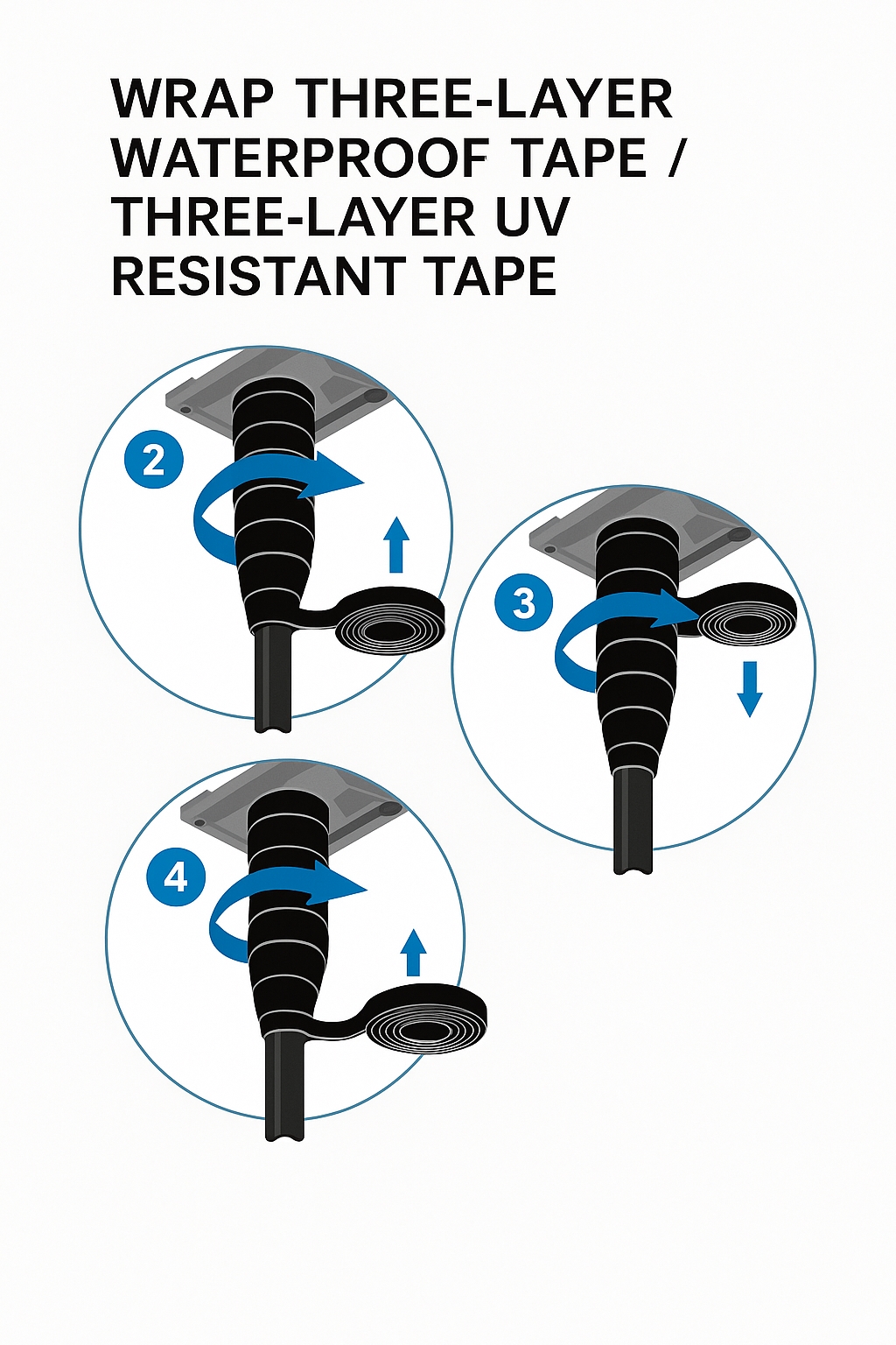
"1+3+3" Tape Method
The "1+3+3" method uses one layer of electrical insulation tape, three layers of waterproof tape, and three layers of UV-resistant tape. The functions are: the insulation layer prevents leakage, the waterproof layers prevent water ingress, and the outer UV-resistant layers protect the waterproof tape from sunlight aging.
Most antenna ANT interfaces are treated with the "1+3+3" method. Before application, clean dust and oils from the cable connector. Then wrap one layer of insulation tape, three layers of waterproof tape, and three layers of UV-resistant tape in sequence. Finish by securing the tape ends with a black UV-resistant cable tie to prevent unwrapping.
Proper overlapping technique is important to achieve effective sealing.
Wrapping the insulation tape
Wrap one layer of electrical insulation tape from top to bottom following the connector tightening direction, using about 50% overlap so each layer covers half of the previous layer.

Wrapping the waterproof tape
Pull the waterproof tape evenly while wrapping. Then wrap three layers in sequence: bottom-to-top, top-to-bottom, bottom-to-top, following the connector tightening direction. Each upper layer should overlap approximately one third of the lower layer to prevent rain penetration. Do not cut the tape during wrapping. After wrapping, squeeze the tape with both hands to ensure firm adhesion between the tape, cable, and connector.
Wrapping the UV-resistant tape
Wrap the UV-resistant tape using the same direction as the waterproof tape. Apply moderate tension while wrapping and maintain about 50% overlap between layers.
Securing tape ends
Leave about 3 mm of excess cable tie at the fastening point to allow for tape expansion in high temperatures.

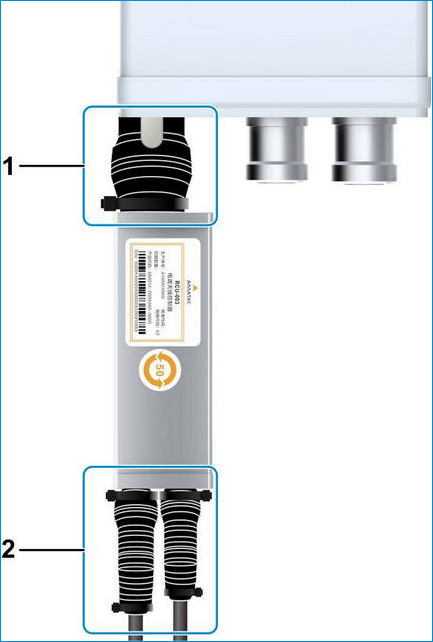
Electrical-Tilt Antenna Interface Waterproofing
For electrical-tilt antennas, the RCUs are connected to the RRU AISG interface. On the RRU side, AISG cables typically do not require additional waterproofing.
On the electrical-tilt antenna side, the RCU ends use different waterproofing methods:
- The RCU-to-antenna connector is waterproofed using the "1+3+3" tape method described above.
- The RCU-to-AISG cable connector is wrapped with two layers of UV-resistant tape. The first UV layer should be wrapped top-to-bottom and the second layer bottom-to-top so that the outermost layer is wrapped bottom-to-top, minimizing the risk of water wicking into the joint.
Unused Connector Waterproofing
Unused RRU connectors also require protection. Fit dust caps and wrap two layers of UV-resistant tape.
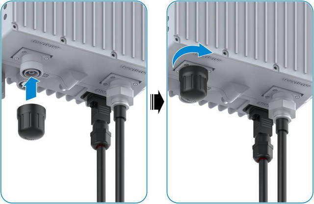
Wrap two layers of UV-resistant tape. Following the connector tightening direction, wrap the first layer top-to-bottom and the second layer bottom-to-top. Wrap so that the tape edge aligns with the underside of the cap, then secure the tape edge with a cable tie.
Storage and Maintenance Notes
- Do not remove protective packaging while equipment is stored in a warehouse. If packaging has been removed, the equipment may absorb moisture and should be powered on within 72 hours after unpacking.
- When powering down equipment for maintenance, avoid extended power-off periods; try not to exceed 72 hours.
Conclusion
Implementing proper waterproofing at antenna and RRU interfaces is essential to maintain reliable operation during severe weather. The common methods outlined here, such as cold shrink tubing and the "1+3+3" tape technique, are widely used in the field to protect connections from moisture, dust, and UV exposure.