ALLPCB


VLAN Basics
VLAN, or virtual local area network, is a technique that logically divides devices within a LAN into separate segments, forming virtual workgroups. It is mainly implemented on switches and routers, with switches being the primary platform.
In 1999 IEEE published the 802.1Q standard draft to standardize VLAN implementations. VLANs let administrators partition a single physical LAN into multiple broadcast domains based on logical groupings. Each VLAN contains a set of workstations with similar requirements, and because the division is logical rather than physical, members of the same VLAN can be located across different physical LAN segments.
Broadcast and unicast traffic inside one VLAN are not forwarded to other VLANs, which helps control traffic, reduce equipment cost, simplify network management, and improve security.
By segmenting an enterprise network into VLANs, administrators can strengthen management and security and reduce unnecessary broadcasts. Workstations in the same VLAN communicate as if they were on the same isolated switch. Without routing, different VLANs cannot communicate, which increases departmental isolation for sensitive areas such as finance or human resources.
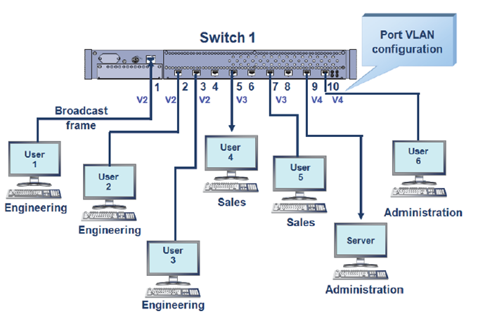
VLAN adds a VLAN tag to Ethernet frames and uses a VLAN ID to group users into smaller workgroups, limiting cross-group access. The benefits include limiting broadcast domains and enabling dynamic virtual group management.
VLAN Division Methods
VLAN implementations on switches can generally be classified into six types:
- Port-based VLAN
- MAC-address-based VLAN
- Protocol-based VLAN (network layer)
- IP multicast-based VLAN
- Policy-based VLAN
- User-defined or non-authorized VLAN
Advantages of VLAN
Key advantages of VLAN technology include:
- Increased flexibility of network connections
- Control of broadcasts on the network
- Improved network security
Case: VLAN Configuration for a Small Company
The company has about 100 computers distributed mainly among four departments: Production (20), Finance (15), Human Resources (8), and Information Center (12).
Network topology:
The core uses three managed Catalyst 1900 switches (named Switch1, Switch2, and Switch3). Each switch connects as needed to several hubs for non-VLAN users such as administrative staff or temporary users. A Cisco 2514 router connects the internal network to the external Internet.
Users are grouped into Production, Finance, Information Center, and Human Resources. Each department will be assigned a separate VLAN to protect departmental resources. Sensitive departments like Finance and Human Resources should have restricted access, so VLANs are used to isolate and protect their networks.
The VLAN groups are: Prod, Fina, Huma, and Info.
VLAN Configuration Process
The VLAN configuration is simple and involves two main steps:
- Name each VLAN group
- Assign VLANs to the appropriate switch ports
Detailed configuration steps:
Step 1: Connect to the switch management console
Use a terminal program to connect to the Catalyst 1900 switch. The switch should already have basic settings configured. Typical initial console output:
1 user(s) now active on Management Console. User Interface Menu [M] Menus [K] Command Line [I] IP Configuration Enter Selection:
Note: The terminal program can be Windows HyperTerminal or an equivalent terminal emulator.
Step 2: Enter the command-line interface
Select the Command Line option to enter the CLI session:
CLI session with the switch is open. To end the CLI session, enter [Exit ]. >
This is the user EXEC mode. It allows viewing the current configuration but not making changes. To modify configuration, enter privileged mode.
Step 3: Enter privileged EXEC and global configuration mode
At the > prompt, enter the enable command to enter privileged EXEC mode, then enter global configuration mode:
> enable # config t Enter configuration commands, one per line. End with CNTL/Z (config)#
Step 4: Set device name and enable password
For security and management, assign names to the three Catalyst 1900 switches and set the enable (privileged mode) password. Example for Switch1:
(config)# hostname Switch1 Switch1(config)# enable password level 15 XXXXXX Switch1(config)#
Note: The enable password should be 4 to 8 characters. The switch uses levels to determine password privilege. Level 1 is the password for entering the CLI; level 15 is the privileged mode password prompted after the enable command.
Step 5: Define VLAN names
Create VLANs on the switches. Commands use the format: vlan <vlan-number> name <vlan-name>. Example:
Switch1(config)# vlan 2 name Prod Switch2(config)# vlan 3 name Fina Switch3(config)# vlan 4 name Huma Switch3(config)# vlan 5 name Info
Note: The above assignments follow the planned VLAN mapping table.
Step 6: Assign VLAN membership to switch ports
Assign VLANs to the switch ports using the vlan-membership command. The command format is:
vlan-membership static <vlan-number> vlan-membership dynamic <vlan-number>
Choose either static or dynamic membership. Static assignment is commonly used. Examples of port assignments:
(1) Switch1 port assignments for VLAN 2 (Prod):
Switch1(config)# int e0/2 Switch1(config-if)# vlan-membership static 2 Switch1(config-if)# int e0/3 Switch1(config-if)# vlan-membership static 2 Switch1(config-if)# int e0/4 Switch1(config-if)# vlan-membership static 2 ... Switch1(config-if)# int e0/20 Switch1(config-if)# vlan-membership static 2 Switch1(config-if)# int e0/21 Switch1(config-if)# vlan-membership static 2 Switch1(config-if)#
Note: "int" is short for the "interface" command. "e0/3" stands for ethernet 0/3, indicating module 0 port 3 on the switch.
(2) Switch2 port assignments for VLAN 3 (Fina):
Switch2(config)# int e0/2 Switch2(config-if)# vlan-membership static 3 Switch2(config-if)# int e0/3 Switch2(config-if)# vlan-membership static 3 Switch2(config-if)# int e0/4 Switch2(config-if)# vlan-membership static 3 ... Switch2(config-if)# int e0/15 Switch2(config-if)# vlan-membership static 3 Switch2(config-if)# int e0/16 Switch2(config-if)# vlan-membership static 3 Switch2(config-if)#
(3) Switch3 port assignments for VLAN 4 (Huma) and VLAN 5 (Info):
-- VLAN 4 (Huma) Switch3(config)# int e0/2 Switch3(config-if)# vlan-membership static 4 Switch3(config-if)# int e0/3 Switch3(config-if)# vlan-membership static 4 Switch3(config-if)# int e0/4 Switch3(config-if)# vlan-membership static 4 ... Switch3(config-if)# int e0/8 Switch3(config-if)# vlan-membership static 4 Switch3(config-if)# int e0/9 Switch3(config-if)# vlan-membership static 4 Switch3(config-if)# -- VLAN 5 (Info) Switch3(config)# int e0/10 Switch3(config-if)# vlan-membership static 5 Switch3(config-if)# int e0/11 Switch3(config-if)# vlan-membership static 5 Switch3(config-if)# int e0/12 Switch3(config-if)# vlan-membership static 5 ... Switch3(config-if)# int e0/20 Switch3(config-if)# vlan-membership static 5 Switch3(config-if)# int e0/21 Switch3(config-if)# vlan-membership static 5 Switch3(config-if)#
After assigning VLANs to ports, verify the configuration in privileged mode with the show vlan command to ensure correct mappings.