ALLPCB


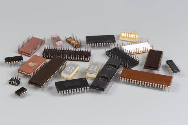
Connecting a microcontroller to dual in-line package (DIP) switches is a common task. DIP switches appear in many designs, from through-hole DIP for breadboard prototyping to surface-mount "piano" types and rotary switches that make reading hexadecimal values easy.
Scope
This article examines rotary switches and how to integrate them into microcontroller designs. The techniques described apply broadly to MCU interfaces.
Rule: Avoid floating inputs
A fundamental rule is to avoid floating inputs. A floating input occurs when an MCU pin is configured as an input but is not tied to a defined voltage. In the following example, when the switch is closed the pin is tied to the supply rail; when the switch is open the pin is left floating.
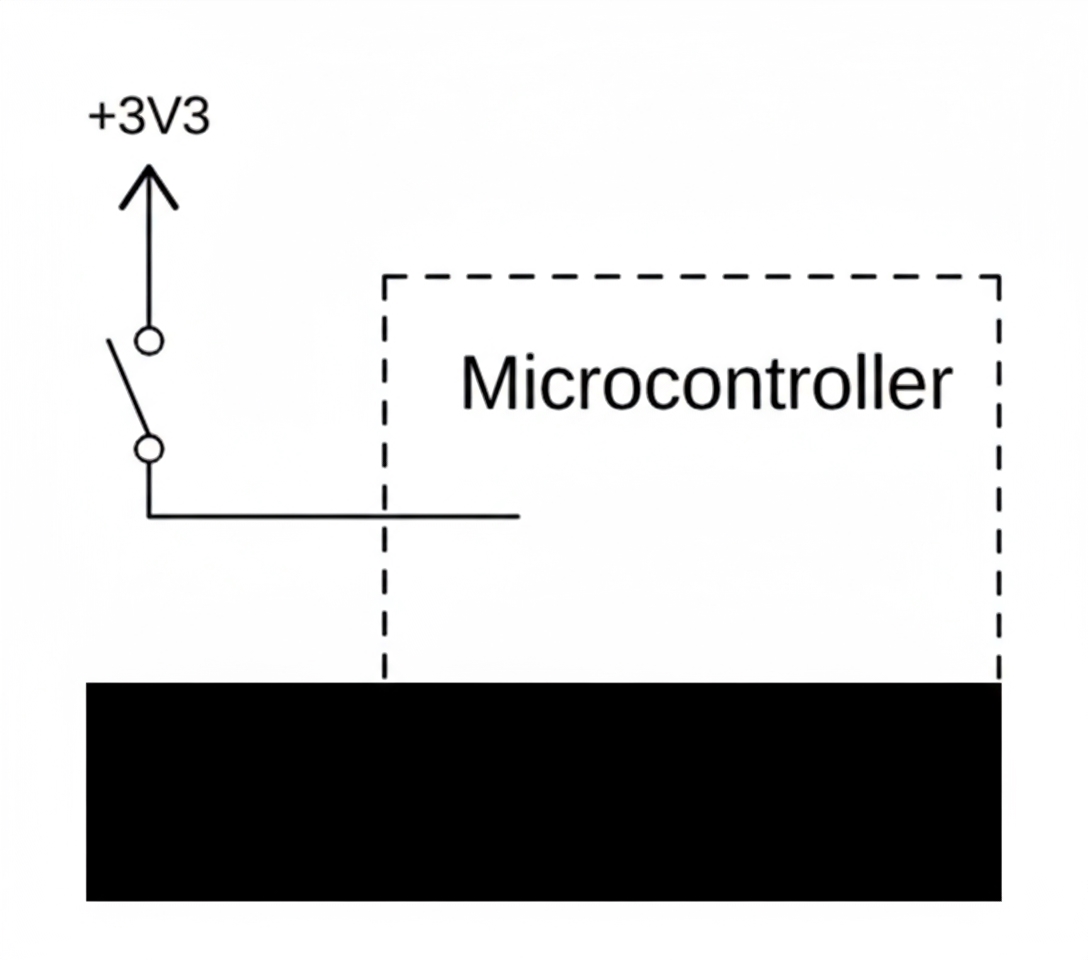
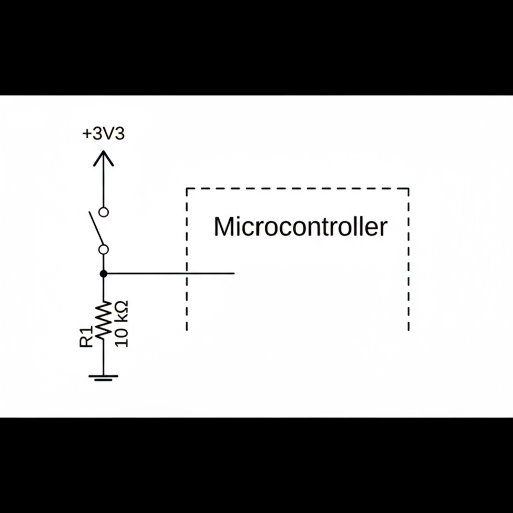
Floating pins are undesirable because they can be interpreted as either logic high or logic low and are highly susceptible to noise. The MCU response may appear random or correlated with adjacent pins. The usual solution is to add a pull-down resistor as shown below: when the switch closes the pin is pulled up to the rail; when the switch opens the pin is pulled down to ground. Ignoring switch bounce for the moment, the MCU then sees a clean input.
Optimized solution: use internal pulls
Most modern microcontrollers include internal pull-up or pull-down resistors on their I/O. This allows a switch to be connected directly to the MCU without external resistors.
Technical tip
Some MCUs provide both pull-up and pull-down options; others provide only one type, with pull-up being more common. These internal resistors are typically weak pull-ups consuming tens to hundreds of microamperes, roughly equivalent to an external resistor in the 15 kΩ to 150 kΩ range.
For example, on Arduino use:
pinMode(SW_PIN_D0, INPUT_PULLUP);
Schematic example
The schematic below shows one way to wire a microcontroller to a switch. Although the example uses a rotary DIP switch, the same design applies to any switch. Note the optional series resistor and optional multiplexing section. Multiplexing allows an I/O pin to perform two tasks; for example, the same narrow interface could be used to read switches or to drive an LCD's D3 to D0. This can reduce MCU pin count and overall PCB size at the cost of added circuit and firmware complexity.

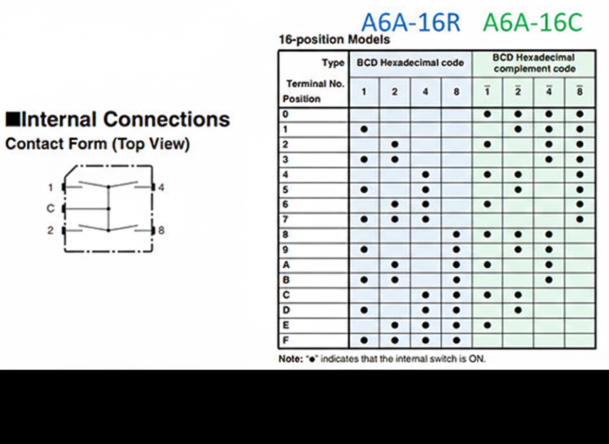
Rotary DIP physical codes
Below are representative hexadecimal codes taken from an Omron datasheet for rotary DIP switches. The A6A-16R and A6A-16C models correspond to a "BCD hexadecimal code" and a "BCD hexadecimal complement" switch configuration respectively.
Logic polarity and software handling
Looking at the MCU schematic with pull-ups, you may encounter inverted logic depending on the switch wiring. From a programming perspective the difference is immaterial: a simple bit inversion in software aligns the values. For troubleshooting or teaching, non-inverted (active-high) versions can be easier to interpret because they present positive logic levels on MCU pins.