ALLPCB


In the fast-evolving world of drone technology, designing flight control printed circuit boards (PCBs) is a complex challenge. One of the most critical aspects is managing power and ground planes to ensure reliable performance. How do you balance power plane design and ground plane design in dense drone PCBs while maintaining signal integrity? The answer lies in careful PCB stackup, impedance control, and optimizing the signal return path. In this blog, we dive deep into these topics, offering practical insights and actionable tips for engineers working on drone flight control systems.
Why Power and Ground Planes Matter in Drone Flight Control PCBs
Drone flight control PCBs are the brains behind a drone’s operation, managing everything from motor control to sensor data processing. These boards are often densely packed with components, leaving little room for error in design. Power and ground planes play a vital role in ensuring stable power delivery, reducing noise, and maintaining signal integrity. Without proper design, issues like electromagnetic interference (EMI), voltage drops, and signal distortion can lead to erratic drone behavior or even crashes.
Power planes distribute stable voltage to components, while ground planes provide a low-impedance return path for signals and help shield against noise. In dense layouts, where high-speed signals and multiple power domains coexist, balancing these planes becomes a delicate act. Let’s explore how to achieve this balance through thoughtful design practices.
Key Elements of Power Plane Design in Dense PCBs
Power plane design is about delivering clean, stable power to every component on the board, especially in high-density drone PCBs where space is limited. Here are some critical considerations:
- Plane Continuity: Ensure the power plane is as continuous as possible to minimize voltage drops. Breaks or cuts in the plane can increase resistance, leading to uneven power distribution. For instance, a split power plane might cause a voltage drop of 0.1V across a high-current motor controller, which could disrupt performance.
- Decoupling Capacitors: Place decoupling capacitors close to power-hungry components like microcontrollers or ESCs (electronic speed controllers). These capacitors smooth out voltage spikes, ensuring stable operation. A typical value for decoupling capacitors in drone PCBs might be 0.1 μF to 1 μF, depending on the component’s needs.
- Power Domains: Drones often operate with multiple voltage levels (e.g., 3.3V for sensors, 5V for controllers). Use separate power planes or split planes for each domain to avoid interference. Keep splits minimal and route signals carefully to avoid crossing these splits.
Effective power plane design reduces noise and ensures that components receive the voltage they need, even under heavy load conditions like sudden motor acceleration.
Ground Plane Design: The Foundation of Signal Integrity
A well-designed ground plane is the backbone of any PCB, especially in drone flight control systems where high-speed signals are common. The ground plane serves as a reference for signals and a return path for currents, minimizing noise and EMI. Here’s how to optimize ground plane design:
- Continuous Ground Plane: Like power planes, the ground plane should be unbroken whenever possible. A solid ground plane under high-speed signal traces reduces loop inductance, which can otherwise cause signal distortion. For example, a discontinuous ground plane might increase loop inductance by 10-20 nH, leading to noticeable signal delays at frequencies above 100 MHz.
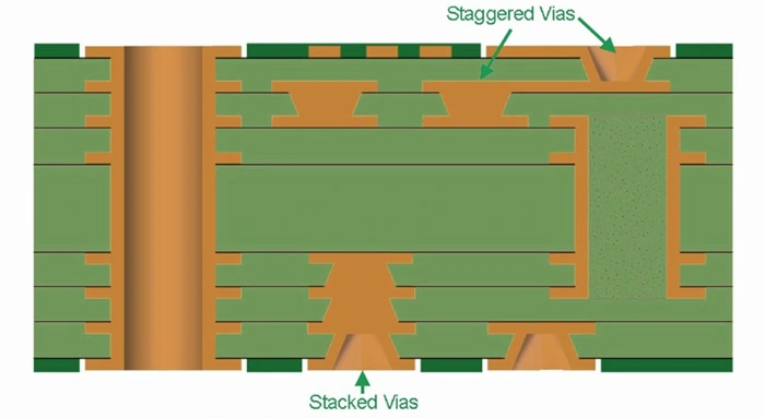
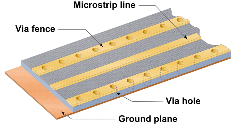
- Via Placement: Use stitching vias to connect ground planes across layers in multilayer PCBs. Place these vias strategically near high-speed components to ensure a low-impedance return path. A general rule is to place a via every 0.5 inches along critical signal paths.
- Ground Plane Separation: In mixed-signal designs, separate analog and digital ground planes to prevent noise coupling. Connect these planes at a single point near the power supply to avoid ground loops.
A robust ground plane design not only improves signal integrity but also helps in managing heat dissipation, which is crucial for drones operating in demanding conditions.
PCB Stackup Strategies for Drone Flight Control Boards
PCB stackup refers to the arrangement of layers in a multilayer board, and it’s a critical factor in balancing power and ground planes. Drone flight control PCBs often require 4 to 6 layers to accommodate dense routing, high-speed signals, and multiple power domains. Here’s how to approach PCB stackup design:
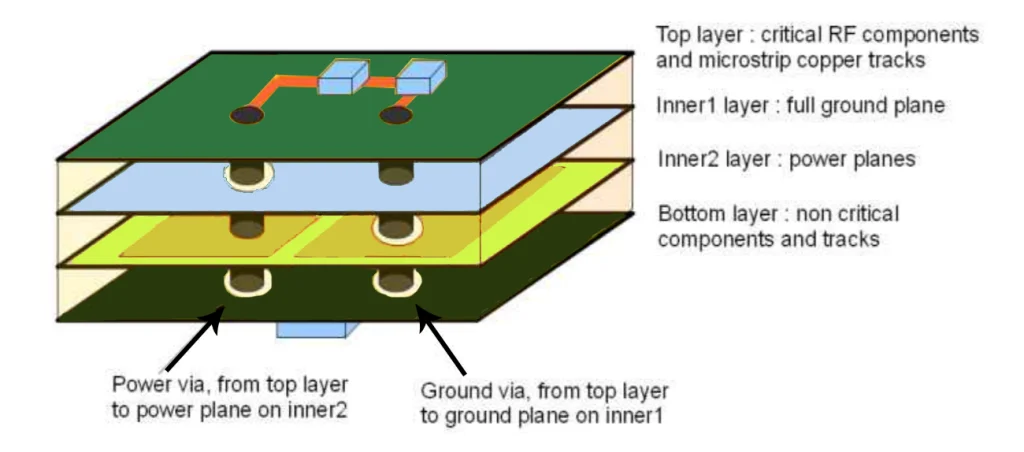
- Layer Allocation: Dedicate internal layers to power and ground planes to minimize interference with signal traces on outer layers. A common 4-layer stackup might be: Signal (Top), Ground, Power, Signal (Bottom). This setup ensures that signals have a nearby reference plane for return paths.
- Plane Proximity: Place power and ground planes adjacent to each other to create a natural capacitance between them. This capacitance helps filter out high-frequency noise. For instance, a dielectric thickness of 0.2 mm between planes can provide a capacitance of about 100 pF per square inch, aiding noise suppression.
- Signal Layer Planning: Route high-speed signals on layers adjacent to a ground plane to maintain a consistent signal return path. Avoid routing signals over splits in power or ground planes, as this can disrupt the return path and introduce noise.
A well-planned PCB stackup ensures that power distribution, signal integrity, and EMI control are all optimized, even in the tight confines of a drone flight control board.
Impedance Control: Keeping Signals in Check
Impedance control is essential for high-speed signals in drone PCBs, where data from sensors and communication modules must travel without distortion. Mismatched impedance can cause signal reflections, leading to errors or delays. Here’s how to manage impedance in dense layouts:
- Trace Geometry: Calculate the trace width and spacing to achieve the desired impedance, typically 50 ohms for single-ended signals or 100 ohms for differential pairs in high-speed designs. For a 50-ohm trace on a 1.6 mm FR4 board with a dielectric constant of 4.5, the trace width might be around 0.3 mm when referenced to a ground plane 0.2 mm away.
- Reference Planes: Ensure that high-speed traces are routed over a continuous ground plane to maintain consistent impedance. Avoid routing over power plane splits, as this changes the reference and alters impedance.
- Controlled Dielectric: Use materials with a consistent dielectric constant for multilayer boards. Variations in dielectric properties can lead to impedance mismatches, especially at frequencies above 1 GHz, which are common in modern drone communication systems.
By focusing on impedance control, you can ensure that signals travel reliably, even in the compact and complex environment of a drone PCB.

Signal Return Path: The Hidden Key to Performance
The signal return path is often overlooked but is crucial for maintaining signal integrity in drone flight control PCBs. Every signal needs a return path to complete the circuit, and in high-speed designs, this path must be as short and direct as possible. Here’s how to optimize it:
- Minimize Loop Area: The return path should follow the signal trace closely to minimize the loop area. A larger loop increases inductance, leading to noise and signal delays. For a 100 MHz signal, a loop inductance of just 10 nH can cause significant distortion.
- Avoid Plane Splits: Routing signals over splits in ground or power planes forces the return path to detour, increasing inductance and noise. If splits are unavoidable, place stitching capacitors across the split to provide a high-frequency return path.
- Use Ground Planes for Return: Avoid using power planes as return paths for high-speed signals. While power planes can carry DC current, they often have higher impedance at high frequencies compared to ground planes, leading to signal issues.
Optimizing the signal return path reduces EMI and ensures that high-speed signals, such as those from gyroscopes or GPS modules in drones, operate without interference.
Challenges in Dense Drone PCB Design and How to Overcome Them
Designing power and ground planes in dense drone flight control PCBs comes with unique challenges. Here are some common issues and solutions:
- Limited Space: With components packed tightly, there’s little room for wide planes or extensive routing. Use multilayer boards to dedicate entire layers to power and ground, freeing up surface layers for components and traces.
- Heat Dissipation: High-current components like motor controllers generate heat, which can affect plane performance. Incorporate thermal vias and ensure ground planes are large enough to act as heat sinks.
- Mixed-Signal Noise: Drones often combine analog sensors and digital processors, leading to potential noise coupling. Separate analog and digital domains on the PCB and use filtering components like ferrite beads to isolate power supplies.
Addressing these challenges requires a combination of careful planning, precise calculations, and strategic use of multilayer designs to balance all aspects of the PCB layout.
Best Practices for Balancing Power and Ground Planes
To wrap up, here are some best practices for managing power and ground planes in drone flight control PCBs:
- Always prioritize continuous power and ground planes to minimize noise and voltage drops.
- Use a well-thought-out PCB stackup to separate signal, power, and ground layers effectively.
- Implement impedance control for high-speed signals by maintaining consistent trace geometry and reference planes.
- Optimize signal return paths by avoiding plane splits and minimizing loop areas.
- Leverage simulation tools to analyze power distribution and signal integrity before fabrication. Tools can predict voltage drops, impedance mismatches, and EMI issues early in the design process.
Following these practices will help ensure that your drone flight control PCB performs reliably, even under the most demanding conditions.
Conclusion: Achieving Harmony in Drone PCB Design
Balancing power and ground planes in dense drone flight control PCBs is no small feat. It requires a deep understanding of power plane design, ground plane design, PCB stackup, impedance control, and signal return path optimization. By focusing on continuity, strategic layer arrangement, and precise signal routing, you can create a PCB that powers your drone reliably and maintains signal integrity, even in the most compact layouts.
At ALLPCB, we’re dedicated to supporting engineers in tackling these complex challenges. Our expertise in high-quality PCB manufacturing ensures that your drone flight control designs are brought to life with precision and reliability. Whether you’re working on a hobby project or a commercial drone, mastering the balance of power and ground planes is the key to soaring success.